1.Introduction
At present, most of the centrifuges used in domestic sugar factories are variable-speed speed-regulating centrifuges. This type of centrifuge has a slow speed increase. The brake uses a brake brake to impact the motor, the motor is easily damaged, and the auxiliary time is long. The noise is high, which limits the increase in production capacity. Since the sugar factory is in an economically underdeveloped area, self-generated electricity, large grid voltage fluctuations, small margins, and strong seasonality of materials require equipment to maintain high productivity, high reliability, maintenance-free, and centrifuge inertia in a short period of time. Large, frequent braking, high speed accuracy requirements, therefore requires the system to have sufficient braking capacity, high requirements for electrical systems.
With the development of frequency conversion technology, the application of frequency converters on sugar separation machines is increasing. The use of frequency converter to drive ordinary three-phase squirrel cage motor can meet the requirements of sugar separation process. Considering that the mechanical characteristics of the separator belong to constant torque and large inertia load, the inverter with constant torque characteristics should be used and the brake braking unit should be configured. The appropriate braking unit should be selected with a certain braking resistor to satisfy the brake system of the separating machine. Dynamic requirements. This paper introduces the application of SINCR C500 series inverters in sugar mill separators. This frequency converter has unique vector control, low speed and high torque output, slip compensation, AVR automatic voltage regulation and other functions. Consistent with the original mode of operation, multi-speed control is used.
2. Process of sugar separator
The sugar separation process of a sugar factory in Guangdong uses centrifugal dewatering. The separator is mainly composed of a cone drum and a driving motor, and the motor shaft is directly connected to the drum. The solid sugar crystallized from the high concentration of sugar water is dehydrated in a cone drum. The process is as follows: the motor starts to rise from zero. At this time, the material also starts to be injected into the drum. It takes about 1 minute to reach 200r/min, and the injected material has reached 1.5 tons. At this time, the material is stopped and the speed is increased to 700r. After running for 1 minute, the speed is increased to 1000r/min. After 4 minutes of operation, the water has been completely dried, and the speed is gradually reduced to stop. The speed reduction process is about 2 minutes. The entire process takes 8 minutes.
3. Braking unit and resistor
3.1. Energy consumption braking: Due to the heavy load (1.5 tons of material), after accelerating to 1000r/min, it should be stopped within 2 minutes, and the braking unit with the capacity equivalent to the inverter capacity must be installed. The unit is actually a voltage hysteresis switch. When the motor is decelerating, the kinetic energy of the load is large, and the voltage applied to the rotor of the motor provides a magnetic field to the motor. The motor becomes a three-phase alternator, and the electricity generated by the generator is rectified by the diode on the inverter bridge. DC charges the capacitor. If the current can be observed, the current flow direction is opposite to that before the speed reduction, indicating that the energy is returned to the inverter by the load. When the charging voltage of the capacitor reaches 710V, the brake unit switch is opened, the current flows to the braking resistor force, and the electric energy is heated by the resistor. The form is consumed. Since the energy is consumed, the capacitor voltage drops, and the brake unit is turned off when it drops to 680V. As long as the braking process is not over, the brake unit is repeatedly turned on and off, causing the load to drop to zero at a steady speed.
3.2. Calculation of braking resistor: In the case of braking resistor braking, the internal power consumption loss part of the motor is converted into braking torque, which is about 20% of the rated torque of the motor. Therefore, the resistance of the braking resistor can be calculated by the following formula:

Where: UC is the operating voltage value of the brake unit, now 710V; TB is the braking torque; TM is the rated torque of the motor; N is the speed of the motor when starting to decelerate, in this case 1000r/min.
In the discharge circuit composed of the brake unit and the braking resistor, the maximum current is limited by the maximum allowable current IC of the brake unit ICBG. The minimum allowable value of the braking resistor is:
Rmin=VC/IC
Therefore, usually Rmin
3.3. Determination of braking resistor: Whether the motor is repeatedly decelerated, the rated power of the resistor is different. In this example, the rated power of the resistor is 24kW, which is naturally cooled. If the rated power of the forced air-cooling resistor can be reduced. Generally, the braking resistor should be a non-inductive resistor with two wires and wounds. Of course, an ordinary box-type resistor can be used. However, a freewheeling diode should be connected to both ends of the resistor. A fast recovery diode can be used with a withstand voltage of 1000V or more.
4. Frequency conversion transformation plan
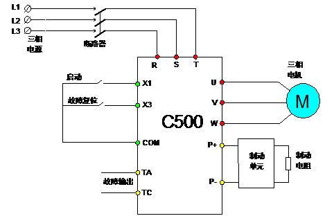
4.1 Main configuration: C500 high performance vector inverter, braking unit, braking resistor.
4.2. The basic electrical diagram is as follows:

5.Conclusion
The scheme realizes the soft start of the system, effectively ensures the system control process and improves the work efficiency, and the energy saving effect is remarkable, and effectively prolongs the service life of the various devices of the system, reduces the maintenance amount of the equipment, and obtains good economic benefits for the customer. Practice has proved that the program has a very broad application prospect in the sugar industry, and has been successfully applied to systems with multiple inverters for frequency conversion.